Archive
Making Nose Gear Upper Intersection Fairing – 5 hrs
Thursday Mar 13, 2014
A couple of days ago I started working on the nose gear upper intersection fairing. I could have purchased a pre-made fairing for about $35 but I have an extended slot in my cowling for the gear strut because I have a three-bladed prop and I need the fairing to extend forward far enough to cover the opening. The pre-made ones don’t do that. So I applied a layer of packing tape to the strut and the cowling to start, including over the slot. I also taped a piece of .025 aluminum to the trailing edge to keep the fiberglass on each side from bonding together along that edge. I bought some blue modeling dough at Michael’s and began forming a blended fairing profile around the strut. This is a pain working on my back on the floor with my hands raised while trying to keep from banging my head into the nose gear.

After getting the profile looking aerodynamic I began laying on fiberglass which I pre-impregnated with epoxy between two layers of plastic sheeting. I put on 3 or 4 layers of 8 oz. bidirectional cloth and let it cure.

The next day I was able to pop it off the cowling thanks to the packing tape. The modeling dough came off with it. It’s pretty ugly at this point.

After an initial trim and light sanding it is starting to look better. The general shape seems OK but it will take several layers of micro over the outside and lots of sanding to get it smooth enough to look acceptable to fly.

On the aft end I saw that it was going to interfere with the lower attachment plate for the cowling so I trimmed the fiberglass away in that area and I plan to apply a few more layers of fiberglass over that area to blend it together. This has not taken as long as I feared to get to this point.

More Fairing Work – 8 hrs
Sunday Feb 9, 2014
This nose wheel fairing is turning out to be more work than I expected. This weekend I wanted to try to wrap up the job of fitting it to the wheel brackets. I needed to drill three holes in the fairing; two for the two bar access and one for access to the air valve. To locate the proper location for the air valve hole I set up a laser level at the height of the valve and I pointed it directly at the end of the valve. You can see the red glow in this photo.

Then I put the fairing back on. The laser now shines directly on the fairing in line with the valve so that is where I drilled. I started out small and worked my way up to almost a inch diameter to fit the camloc access door I bought at ACS.
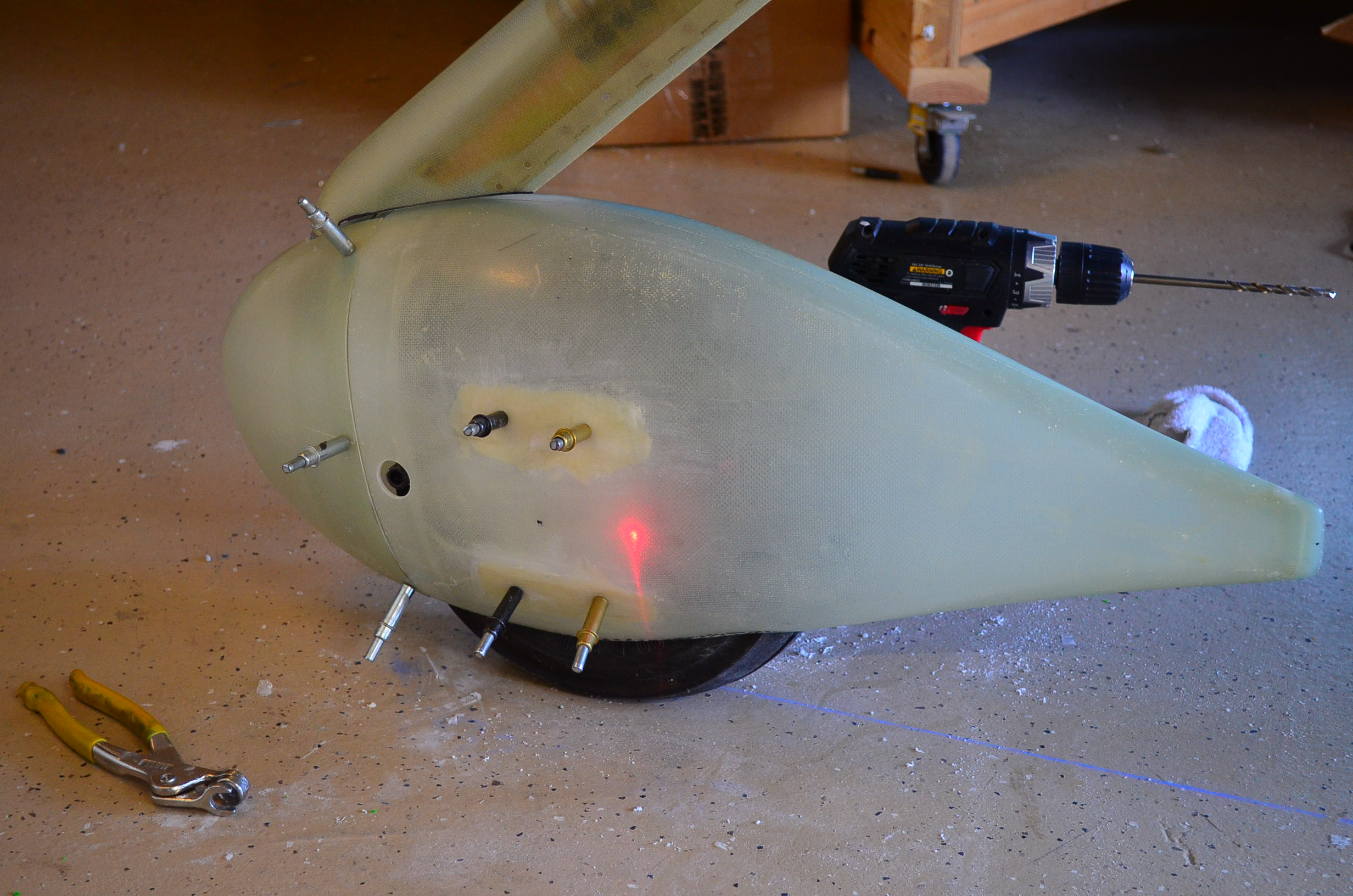
This next photo shows the fairing after I had installed the access door and drilled both holes for the tow bar.

I did a final trim of the cutout for the wheel to make sure I had adequate clearance then I mixed up some epoxy and painted on a layer inside the fairing to seal the surface with a non-porous layer. Then I set this out to cure.

I resumed work on the main gear leg fairing by installing the hinge which is used to close up the aft edge. This was basically the same process used on the nose gear leg fairing. I also cut the notches for the hose clamp that will hold the fairing to the gear leg.

I then checked the fit on the gear leg. I made another trim cut on the bottom edge and now this looks good to go. Not shown here are some reinforcement patches I laid up inside the left main wheel fairing in the areas where the brackets mount. I put down two or three layers of fiberglass to even out the surface of the fairing and make it more parallel to the bracket surface. I’ll still have to form epoxy/flox shims between the fairing and the brackets later to get the fit I want.

I also went out to Corona to look at hangars on Saturday. My search for a home base has officially started.
Preparing to Install Main Gear Fairings – 8 hrs
Saturday Feb 1, 2014
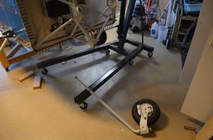
This weekend was my first chance try out the jack stands I built to lift the fuselage and take the weight off the landing gear. This is needed to install and align the main gear fairings (pants). I used the engine hoist to lift the engine mount to level the longerons so the aircraft support is on three points. It is quite stable and I don’t have any concerns about the stands tipping over so I can leave the airplane this way for a while.

First thing I needed to do was install the wheel fairing support brackets. I fit these to the wheels a long time ago but I found that I needed to trim down the three tubular spacers about 0.1 inch to get the gap to the bracket set in the .032 -.094 range called for on the drawing. That took a while but I got everything back together again with the brackets installed and ready to receive the fairings.

I dropped a plumb line from the center of the firewall and another from the tie down ring on the tail and snapped a chalk line between them to mark a centerline for the aircraft. Then I measured out about 40.25 inches in tow places and snapped another chalk line parallel to the centerline but passing through the centerline of the tire where it touches the ground. I did this on both sides of the aircraft. These are my lines to which the wheel pants will be aligned.

Back on the nose gear fairing, I mixed up some epoxy with flox and I gooped it up in between the nose gear fairing and the brackets. These brackets don’t sit flush on the fairing surface and the epoxy is to form a shim that makes the connection solid without distorting the fairing. After installing the wheel fairing I checked the alignment and then left it alone for about 3 hours while the epoxy cured. I switched out the clecos after that to make sure I did not epoxy those in place and let it cure another 2-3 hours.

After that I took off the leg fairing and started fitting the hinge that holds the rear edge together. Here you see it drilled and cleco’d to the fairing. I trimmed the hinge to length but I left the hinge pin long for now.

Bonded Nose Gear Strut, Installed Oil and Fuel Pressure Manifold – 4.5 hrs
Saturday Dec 15, 2012
I have read reports on the forums that some RV owners have had problems with the nose gear bolt loosening over time and/or the bolt hole yielding allowing the nose gear to rotate slightly around the strut axis. Some builders have opted to put a large tapered pin in place of the 5/16 bolt requiring the holes to be reamed together at assembly. There are a lot of RVs flying without this problem apparently so I decided to stay with the Vans standard design. There is another way to strengthen the joint and that is to epoxy bond the mating surfaces between the strut and the engine mount around the bolt hole. I decided to go this route. The first step was to remove the nose gear strut from the engine mount.
I bought some Devcon epoxy mix at the hardware store. I chose this epoxy because it is strong (2500 psi) and it is rated for use up to 200 F. That relatively low temperature means I can easily heat the strut up and weaken the bond if I every need to remove the strut again. Other epoxies rated up to 500 F would make that very difficult. I am thinking at the gear bolt should stay well below 200 F in service.

I cleaned the journal surfaces of the strut and the mount with solvent to remove any grease. Then mixed the epoxy and rubbed a generous layer on the inside diameter of the mount. Then I inserted the gear strut half way. I applied a thin layer of grease to the lower strut journal which will not be bonded, then pushed the strut all the way in. A good bit of epoxy oozed out so I am confident I got an adequate amount in the joint. Then I just inserted the bolt and torqued up the nut. I cleaned up the excess epoxy. Here is the bolted joint starting to cure. I can’t get the bolt in from the inside of the cockpit as prescribed in the plans because the hole is slightly too high. I don’t know how that happened because I think I measured it accurately. I may be in the tolerances of the engine mount or perhaps I should have used a 1-inch hole (the plans call for a 3/4 inch hole). So I inserted the bolt with the head up. I have read that others have done this also. I may have to punch a dimple in the hole plug to clear the nut head.

I also assembled the manifold for the oil and fuel pressure sensors. First I had to rivet the F-745 ribs to the firewall. Then I installed the fittings and hole plugs on the manifold using Permatex #2 to seal the threads. I was worried that the fittings may not want to point in the right direction when I tightened them up but they came out fine. Maybe I was just lucky. If so, I’ll take it. Then I mounted the manifold to the firewall using two AN3 bolts. Finally, I installed the oil pressure hose from the kit with two Adel clamps to secure it along the top of the firewall recess.

Drilling Axles for Cotter Pins – 2 hrs
Thursday Dec 13, 2012
The nose gear has a couple of big belleville washers that preload the vertical pivot bearing axially. This eliminates slop but more importantly causes frictional damping to prevents the nose wheel from doing the shimmy at high speeds. The level of preload is set by adjusting the pivot bearing nut until the breakaway drag on the pivot bearing is about 22 lbs measured along the wheel centerline. The scale for measuring this does not come with the kit so I went on Amazon and found a digital luggage scale that measures up to 75 lbs. It was only about $7 so I ordered it about a month ago anticipating this day. I can also use it to weigh luggage.
Here is my setup for measuring the breakaway friction of the pivot bearing. I used safety wire to make a loops that attach to the nose gear fairing brackets on each side. The nose wheel is off the ground in this photo about an inch so the pivot axle is vertical. I adjusted the nut until the breakaway force was about 22 lbs in each direction then I rotated the wheel through +/-30 or so about fifty times to make sure everything was seated and rubbing surfaces were broken in. Then I readjusted the nut for 22 lbs again. In repeated measurements the results varied somewhat but in the end I measured about 22 lbs in one direction and about 24 in the other direction with each measurement varying about +/-0.5 lbs from one measurement to the next. Then I drilled the holes in the axle for the cotter pin. That was a pain in the neck. The axle is steel and it is pretty hard. Going at low rpms and using plenty of lube it took quite a while to drill through each side and I broke one drill in the process. Nevertheless I got the holes drilled and deburred and the nose gear is now permanently mounted to the axle with the cotter pin installed.

For the main landing gear I had to raise the nose of the fuselage slightly with the crane to get the weight off the gear. I started with the left main gear. These use tapered roller bearings with seals that offer a fair amount on rolling resistance (at least until the seals wear in a bit). The objective here is to tighten the axle nuts enough to remove all axial play in the bearings but not so tight as to cause excessive loads on the bearings. The Matco instructions say to tighten the nut until the seals no longer rotate with the wheel as it is turned then tighten to the next cotter pin position. Well, there are no cotter pin positions yet because they are not predrilled so I tightened the nut about 15-20 degrees past where the seal stopped turning. I also checked to make sure there was no freeplay in the bearings at this preload. Then I started drilling with a 12 inch #30 drill through one of the pin holes of the nut. Once I drilled far enough that the hole center was well established I took the nut and wheel off the axle and finished drill through the first side with a new 1/8 inch cobalt drill bit. I cleaned up the burrs and reassembled it to set up to drill the opposite side. To make sure the hole I just drilled was aligned to the hole in the nut I pushed a 1/8 inch solid rivet though the aligned holes in the nut and the axle to key them together before drilling on the other side. Then I repeated the drilling process for the opposite hole starting with the 12 inch #30 drill until the hole center was well established. After I took the wheel off again and had drilled through the axle I ran the drill through both holes at the same time to make sure the cotter pin could pass through both sides. Then I just cleaned up the burrs with a tiny jewelers file and put it all back together again. The cotter pin is currently slipped through but I won’t bend it until I am satisfied the wheel is staying on.

This Bird Has Legs – 8 hrs
Saturday Dec 1, 2012
Today was one of those rare days where a bunch of significant things were completed. I started this morning working on the ELT mount. The parts needed to be primed so I scrubbed all the parts with Simple Green, rinsed and dried them. The weather was not great this morning and the humidity was kind of high but I was able to get a decent coat of primer shot onto the parts in the paint booth. After drying a while I riveted them together with the nutplates for the ELT tray. Here is the bracket by itself.

And here is how it looks with the ELT tray installed. The ELT traps are clamped down under the tray by the mounting screws.

I installed the bracket with the tray attached into the fuselage using CS4-4 pop rivets and installed the ELT to the tray. I’m guessing it is stiffer than the Vans bracket because it ties directly into those stringers without the large flat surface of the Vans bracket. This mount sure seems stiff. It also does not interfere with the rudder cable and it keeps the center of gravity as far forward as possible.

Next I installed the Dynon remote transponder unit. It also has a tray which I mounted with three screws to the center rib behind the pitch autopilot servo. I drilled the holes in the rib and used locknuts to install it. This did not take long once I got my less-than-flexible body back there where I could reach this area. The transponder just snapped into the tray with a wire retaining clamp on the aft end. Next step with the ELT and transponder will be making coax cables and running wiring.

Several months ago I purchased an engine crane at Harbor Freight in preparation for hanging the engine. Today was the day that I opened the crate and assembled this thing. It took about 45 minutes to put all the pieces together and get it operating. I have to say I am impressed with the quality of this thing. It lists for $200 but I bought it with a HF coupon for $100 and at that price it is a steal. It is perfect for this job and it looks pretty good too. I just wish I had more space to store it.

I didn’t really plan this in advance but since I had the crane operating I lashed it to the engine mount and lifted the front end of the fuselage. That gave me enough clearance to insert the nose gear which has just been sitting in the corner anyway. I had to jiggle it quite a bit to get the bolt hole aligned but I got it in. At that point I had to decide to go ahead and put the two main gear legs on or remove the nose gear for another day. I thought, “It’s time to give this bird some legs.” With the crane attached I just lifted the front a little further and I could slide the main gear legs into the sockets and bolt them in. Wow, it is cool that this is done – it’s a major milestone.

One lesson learned – I buggered up the threads on one of the gear leg bolts trying to get it in before the holes were perfectly lined up. After that I got smarter and went to the hardware store a picked up a 3-inch long, 5/16 diameter bolt that I ground down to make a tapered drift pin (see below). Once I got the holes close I tapped this pin in to center everything up before installing the real bolt. I will have to order a replacement for the one bolt I buggered.

Installed Nose Wheel – 1 hr
Tuesday Oct 16, 2012
You may have noticed in my last post that the nose wheel was missing. That is because I decided to send it out to Anti Splat Aero in San Bernardino for a wheel bearing mod. The stock bearing setup has been widely discussed on the Vans Air Force forums and some of the shortcomings of the high rotational drag and the effects it has on wheel shimmy. The drag is partly because of the bearing seals and partly because there is no rigid axle, only an axle bolt that passes through the wheel. The bearing preload is dependent on how much torque you put on the axle bolt.
I also learned that the tires are often out of balance and out of round which also contributes to shimmy. The Anti Splat Aero mod replaces the tapered roller bearings with a pair of sealed ball bearings and a rigid axle spacer that allows you to torque down the axle bolt fully without changing the bearing preload, and the bearings are supposedly lubricated for life. Anti Splat Aero also dynamically balances the tire on the wheel and shaves off the outer surface on a lathe to true up the tire relative to the rotation axis. Both of these should make the tire roll much smoother on the tarmac.
You can do you own research but I decided it was worth $250 plus shipping to get this mod done now. I just don’t want to deal with shimmy during flight test. Here is a photo of the wheel as it came back from Anti Splat Aero (by the way they turned it around in one day so my wheel was gone less than a week including shipping time). The spacers were also modified to fit the new bearings.

I checked the torque on the wheel nuts, set the time pressure at about 35 psi and installed in the wheel fork.

Then I installed the gear leg into the fork and just made the nut snug. I need to get a grease gun to pack the swivel bearing and then set the preload to the proper level per the instructions before drilling the axle for the cotter pin.

Nose Gear Work and Fuselage Skin Riveting – 6.5 Hrs
Sunday Oct 14, 2012
Here is a summary of the weekends work activities. I started with the U-630-1 front wheel fork. This part needed some deburring and scuffing to prepare it for painting. I also masked off the threaded holes and the bearing hole to keep the paint out of there.

Since I was getting ready to shoot primer I prepared the U-713C brackets which are used to mount the wheel pant. This required a modification to cut the wide slot down the middle of each part. In addition I deburred and scuffed the U-810-L and -R, and the U808 (2 ea) which are brackets for the main gear wheel pants.

I fired up the pant gun and sprayed a good coat of Ekoprime on the surfaces. Here are the parts after they had dried for an hour or so.

Later I picked up a can of Rustoleum high performance white enamel to paint the front gear fork. This part will be exposed to the elements and if I don’t install the wheel pants before first flight will be visible for a while so I wanted to paint it to match the gear strut, more or less. The Rustoleum fit the bill because I did not want to spend a load of cash on getting it powder coated. Here is a shot of the fork after painting. I left this to dry over Saturday night.

Sunday morning I assembled the fork and U-713C brackets along with the axle bolt and the two screws that are used as rotational stops just to make sure everything fits together OK.

The canopy latch fingers are alloy steel so I painted them with Jetflex to match the interior paint. Those dried over night also and I installed them with the lock nuts this afternoon. I

Later Scott came over and we did some riveting on the top fuselage skin. I need to get this section done in order to complete the installation of the rear window. The down side is now it will be harder to work in the aft fuselage cone because I will have to crawl inside for everything like installing the ADAHRS. Oh well, the price of progress. We riveted everything up to the F-706 bulkhead which I can probably finish solo.


A really nice example of an RV7A by Byron Graves. I hope mine looks half this good

Build Phase
