Archive
A Tale of Two Suppliers – 9 hrs
Sunday April 27, 2014
This is a tale of two suppliers. The first is Build-Plates.com which is a maker of data plates. I found Build-Plates.com in a Google search on the web. They advertise plates for aviation and other markets like classic cars.I liked the look of their plates and the price was attractive so I ordered one. It arrived in less than a week and I was even more pleased with how it looked when I saw it in person. I installed it a few weeks ago and was happy until I read in a DAR inspection checklist that it had to be fireproof. The plate I ordered was aluminum and clearly would not survive a fire. In frustration, I fired off an email to the company complaining that they should have told me it was not a legal data plate and it should be steel. To my surprise I received a response from the owner of the company within a day saying I was the first to call this to their attention, he had done some research and found that the FAA had changed the regulations on data plates a few years ago and they had missed it. They would send me a refund and were investigating new materials. I told Scott the owner that I was interested if they could make it fireproof. To make a long story short, I received a replacement data plate in about a week in a brass plated steel material. I actually like the look with a brass background color in a field of black anodize (see below). I commend Build-Plates.com for how they responded to my complaint and could not ask for more. I’m not sure how the DAR inspector will respond to this material. It’s not like other data plates I have seen. Scott claims it is fireproof but the anodize looks like it could be a painted surface which would burn off. I asked Scott if he could send me a report on the flame testing he has done on this material. I have not heard back on that yet but it would be handy if the DAR asks. All in all, I would recommend Build-Plates.com but stay tuned to find out if mine passes inspection.

The second supplier is ACK Technologies. They make the E-04 ELT I installed behind the baggage compartment. I bought my ELT for just under $600 in November of 2012. I needed it at that time to make a custom shelf to mount it but I wasn’t going to install it until further in the build process. I wired it up recently and I did not test it until two weeks ago when I found it was completely dead. I checked the battery voltage and it was only 0.2 volts, not 12V as it should be. Not good. So I called the company and the representative I talked to said mail it in and they would repair it under the 2-year warranty. I packed it up and sent it to the factory in San Jose and three days later I got a call telling me I must have triggered the ELT at some point and let it run dead. It was going to cost me $65 for a new battery. But I argued I never turned the ELT on because I had not registered it until two weeks ago and since it was switched off I can’t see how I could have triggered it. The switch was still off when I went to test it two weeks ago so I hadn’t accidentally turned it on. The only thing I can think of is it may have been dead when I received it in 2012 from Chief Aircraft. Since I did not test it then I never realized it. After talking to the technician for a few minutes he agreed to put a “used” battery in it with the same shelf life as my old battery and send it back to me at no charge. That’s more than fair and I appreciate ACK Technologies standing behind their product. The lesson I learned for next time is to test the ELT as soon as I receive it. And I’ll do that when I replace the battery in 2017.
This weekend was the time to charge the brake system with fluid and bleed it. I purchased a quart of Mobil 1 synthetic automatic transmission fluid on the advice of many on VAF instead of the typical Royco 782. I also bought a pump-type oil can off Amazon along with some vinyl tubing from Home Depot. In short I connected the oil can to the brake bleeder valve via the vinyl hose and started pumping fluid into the lines from the caliper to the reservoir. The right ride was easy. The fluid flowed in quickly and in a minute or two I had pushed fluid into the reservoir. When I closed the bleeder valve and check the firmness of the right pedals they were rock hard. Charging the left side was much harder. The fluid did not want to flow easily with significant back pressure for unknown reason. It took a lot of slow pumping to get the fluid all the way through and it was hard to push out the bubbles visible in the lines. When I closed the bleeder valve and check the firmness of the left pedals they were a little squishy. And when I pumped them I saw bubbles come out of the master cylinders. I disconnected the hose at the top of the landing gear and pumped fluid through that line and the brake caliper but it was still hard to pump. It must be some restriction in the caliper. I reconnected the hose and pumped the brake pedal with the bleeder valve open to push fluid backward through the caliper hoping to discharge anything that might be in the line. That seemed to help a little. So I pumped more from the bleeder valve to the reservoir and after more time than I expected all the bubbles were gone and both sets of pedals are now very hard.

To catch any overflow from the reservoir I attached a straight AN fitting in place of the vent screen on top. To that I attached a short aluminum tube with a flaired AN fitting and a vinyl hose going into a clean water bottle. This worked perfectly to prevent an overflow. When I was done I opened one of the bleeder valves and pumped the pedal enough to drain any excess in the vinyl tube back into the reservoir so it would not spill out when I took the AN fittings off. Then I pumped enough out of the reservoir with a syringe to leave the fluid level about an inch below the vent screen.

I had a couple of plastic lines that are close to rubbing against the braided stainless steel lines so I put some split vinyl tubing on them for protection.

My wife helped me remove the canopy one last time (I hope) to install the rubber seal strips and to make it easier to rivet the front top skin on.

Installed Rudder Fairing, etc. – 9 hrs
Sunday April 20, 2014
Easter weekend, so happy resurrection day! I had the chance to fly an RV-7 (N223J) on Saturday with Jake Lewis, a neighbor in Mission Viejo and resident of a hangar at KAJO. We flew out to San Clemente and up the coastline to Huntington Beach. He let me pilot from the right seat most of the time. It was a blast. So much different than the C172 and I am anxious to put the spam can days behind me.
Back at home after lunch I completed the final installation of the lower fairing on the rudder. I had drilled pilot holes but I needed to install nutplates and countersink the fiberglass for Tinnerman washers. Here is a view of the nutplates installed along the attachment strip.
And here is a view with the fairing installed with the washers. I guess I could have spaced the screws out a little more and used fewer. This thing is on solid.

I also made and installed a tab for the local electrical grounding of the strobe light. I needed to ground the cable shielding on both ends to minimize EMI concerns but there was no convenient place to screw down the ground lug. So I made a tab, installed a nutplate on it, and riveted it to the bottom rib of the rudder.

On Sunday evening after getting home from my daughters place I installed the nutplates on the horizontal stabilizer for the empennage fairing. Here is a view of the fairing test fit.

The list of things to do before moving to the airport is getting shorter and shorter.
Installed Fitting In Fuel Tank Access Plate – 8 hrs
Sunday April 13, 2014
When I ran the purge line to the right fuel tank access cover I had to remove the cover to install a fitting. That is when I realized that the fitting interferes with the anti-hangup guide on the inside of the cover. So I ordered another blank cover from Vans along with a ProSeal kit and some Poly-Gone AG300 ProSeal remover. Yesterday I put the right wing on the work bench so I could get to the cover to work on it. It is not accessible in the wing rack.

PolyGone is a jelly-like substance that breaks down ProSeal. I brushed it onto the rib of the fuel tank and let it work for a few minutes. Then I scraped it off with a piece of plastic. After a few iterations and cleaning with acetone it looked pretty good. It should be adequate for a good seal. I also went over it with scotchbrite again to make sure to get good adhesion with the new ProSeal.

I had to remake the flop tube anti-hangup guide inside the cover. Since the purge line fitting ended up right in the middle of the guide I put a hole in it to allow the fuel to pass through without significant obstruction. I put a bulge in the guide to compensate for the area removed by the hole. I also used the guide support to capture the AN fitting so it cannot rotate on the inside of the cover (since I’ll never be able to put a wrench on it again). The support is riveted to the cover so the fitting cannot turn.

I mixed up the small ProSeal kit and applied some to the interfaces as I riveted the cover and guide parts together so there should be no leaks around the rivets. Then I applied a layer to the mating surface on the rib and screwed on the cover. I put a dab of ProSeal on each screw also. I tightened up the screws and let it sit for the ProSeal to set up. I will leak test it in a few days.

I also started modifying the nose of the engine cowl to provide a tiny bit more clearance for removing the lower cowl with the 3-blade prop. I had between 0.20 and 0.25 inch clearance all around and the gap looked nice but it makes it that much harder to remove the lower cowl. Since I will be removing the cowl frequently during Phase 1 I decided to modify this now while it is easier to do. I want another .06 to .12 clearance if possible. I sanded the nose down with a long sanding block. Since I sanded through the top layer of fiberglass into the foam wedge I had added a long time ago I chipped out the foam.

After I sanded down to my goal I mixed up some flox and filled the open area where the foam was as a base for a top coat of micro.

Followup: On Tuesday night 4/15 I finished filling, sanding and priming the cowling. It’s hard to see the difference in the photo but here is the finished modification with the spinner plate on. The gap is now a little bigger and it is slightly wider toward the lower cowl since that is the hard one to remove. In this process I also learned that half the battle of installing and removing the lower cowl is getting the rubber seal strips on the inlets out of the way. I found that if I pulls those back with blue painters tape I could raise and lower the cowl much more easily without scraping the spinner as much. Eventually I’l get the process down to where it is not a pain.

Sanded and Applied Primer to Gear Fairings – 8 hrs
Sunday Mar 16, 2014
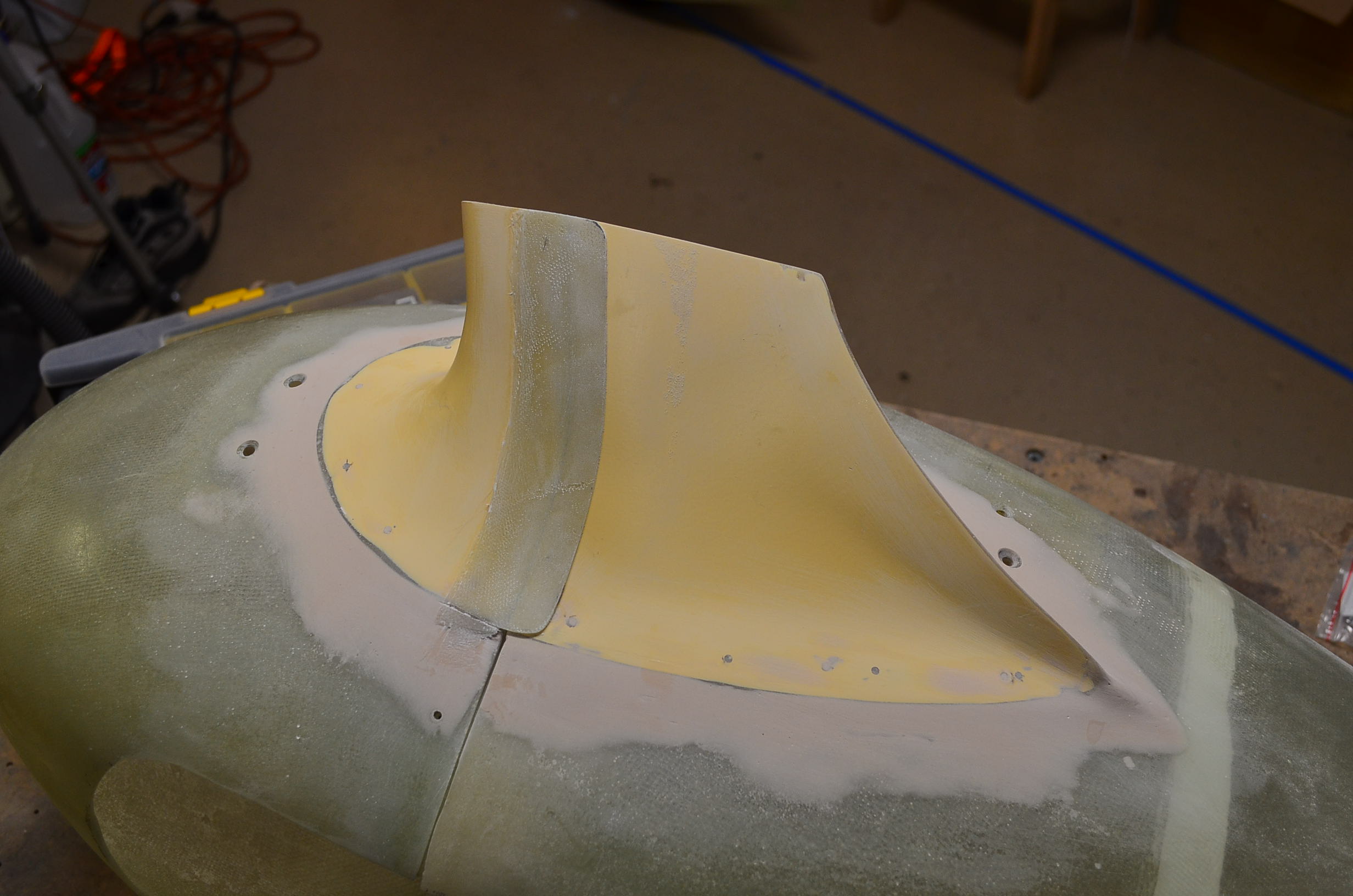
Continuing to work on my gear leg fairings, I applied a layer of epoxy/micro to the nose gear upper intersection fairing to smooth out some of the waves and irregularity that came with the layup over the modeling dough. That, of course, was followed by lots of sanding. One coat got me 90% of the way there, so I applied more micro in a few spots to finish it off. Here is the end result, ready for a coat of primer.

Next I installed the right brake hose and taped it to the gear leg with split tygon tubing spacers at each end and the middle.

One more check of the fit of the right leg and wheel fairings to confirm that this set is ready for primer.

An optional step was to mold a little aerodynamic lip onto the front shell of the nose gear fairing where the cutout is for the strut. This directs the airflow up around the strut instead of directly into the slot. I applied a layer of packing tape to the cutout to form a ramp and then two layers of bidirectional cloth to start and let that cure in the basic shape. Then I applied a fillet of epoxy/micro along the front edge and smoothly blended that out on the side. This only took one iteration of sanding to get a decent shape.

Here is a side view of the front shell where you can see the smoothly blended lip.

Next came a major primer session. I used UV smooth prime which is thick and a pain to spray but it cover pins holes better than Ekoprime and provides a UV barrier for the fiberglass. It also sands easily and gives a really smooth surface. I had to load my spray gun several times to get all eleven of these part primed including the empennage fairing which has been sitting around a while waiting for primer.

Here is another close up view of the nose gear fairing front shell where you can see how the lip turned out.

3/23/14 Update: Here is how the nose gear upper intersection fairing looks after I match drilled it to the cowling. I still need to install nut plates on the cowling and countersink the fairing for flat head screws.

Making Nose Gear Upper Intersection Fairing – 5 hrs
Thursday Mar 13, 2014
A couple of days ago I started working on the nose gear upper intersection fairing. I could have purchased a pre-made fairing for about $35 but I have an extended slot in my cowling for the gear strut because I have a three-bladed prop and I need the fairing to extend forward far enough to cover the opening. The pre-made ones don’t do that. So I applied a layer of packing tape to the strut and the cowling to start, including over the slot. I also taped a piece of .025 aluminum to the trailing edge to keep the fiberglass on each side from bonding together along that edge. I bought some blue modeling dough at Michael’s and began forming a blended fairing profile around the strut. This is a pain working on my back on the floor with my hands raised while trying to keep from banging my head into the nose gear.

After getting the profile looking aerodynamic I began laying on fiberglass which I pre-impregnated with epoxy between two layers of plastic sheeting. I put on 3 or 4 layers of 8 oz. bidirectional cloth and let it cure.

The next day I was able to pop it off the cowling thanks to the packing tape. The modeling dough came off with it. It’s pretty ugly at this point.

After an initial trim and light sanding it is starting to look better. The general shape seems OK but it will take several layers of micro over the outside and lots of sanding to get it smooth enough to look acceptable to fly.

On the aft end I saw that it was going to interfere with the lower attachment plate for the cowling so I trimmed the fiberglass away in that area and I plan to apply a few more layers of fiberglass over that area to blend it together. This has not taken as long as I feared to get to this point.

Intersection Fairings – 20 hrs
Sunday Mar 2, 2014
I was out of town last weekend with the wife and for a couple more days this week on business so progress was delayed.
With the gear leg fairings aligned it was time to start installing the lower intersection fairings on the wheel pants. I purchased mine from Cleaveland Aircraft but they are actually made by RVbits. These are supposed to be better quality than the Vans parts. After aligning them to the leg and wheel fairings I match drilled a set of #40 holes to cleco them in place. I then marked a line to cut the intersection fairing into three pieces so it can split with the front and read wheel fairing sections. After wrapping the gear leg fairing with packing tape I mixed up some epoxy with heavy flox and bonded the three pieces back onto the wheel fairing as well as bonded the aft edges of the intersection fairing together. I did this all in place on the gear leg to make sure everything was fitting well. Here is one clecoed together and set up to cure.

After the epoxy was set I sanded the surfaces to remove excess epoxy. I applied more packing tape over the aft section of the intersection fairing and laid down three layers of fiberglass overlapping the seam between the front and rear sections to make flaps attached to the front section that overhang the aft section along the gear leg fairing so the air stream cannot get under the aft fairing and lift up the forward facing edge. I took this picture after I removed the fairing sections from the landing gear and clecoed them back together. Here you see the raw fiberglass layup.

With the two sections separated you can see the fiberglass is bonded to the front section and simply overlaps the aft section. The edges of the layup are still raw.

After trimming the edges to leave 1/2 inch overlap and sanding the surfaces the parts look like this.

Here I put it back together again to show the finished overlap on the bottom edge.
When I was happy with the flaps on the left side fairing set I mixed up more epoxy with micro and smeared it on to smooth out the transitions between the parts including the front and rear wheel fairings which are not very flush along the seam. This photo is before sanding the micro.

I received two hoses I ordered from TSFlightlines for the brake lines down the landing gear legs. I installed the left hose to verify the length. It looks good so I installed it using three short pieces of plastic tubing and electrical tape to strap it to the leg.

I sanded the micro on the left wheel pant and intersection fairing using several coats of epoxy to get it well blended and smooth. I also sanded the entire exterior of the both the left wheel and leg fairing. Then I installed K1000-6 nutplates on the aft wheel pant section for the screws that hold the two sections together. After more hours of work than I expected this set is finally complete including the lower intersection fairing and is ready for primer. I just need to get the right set up to the same point.

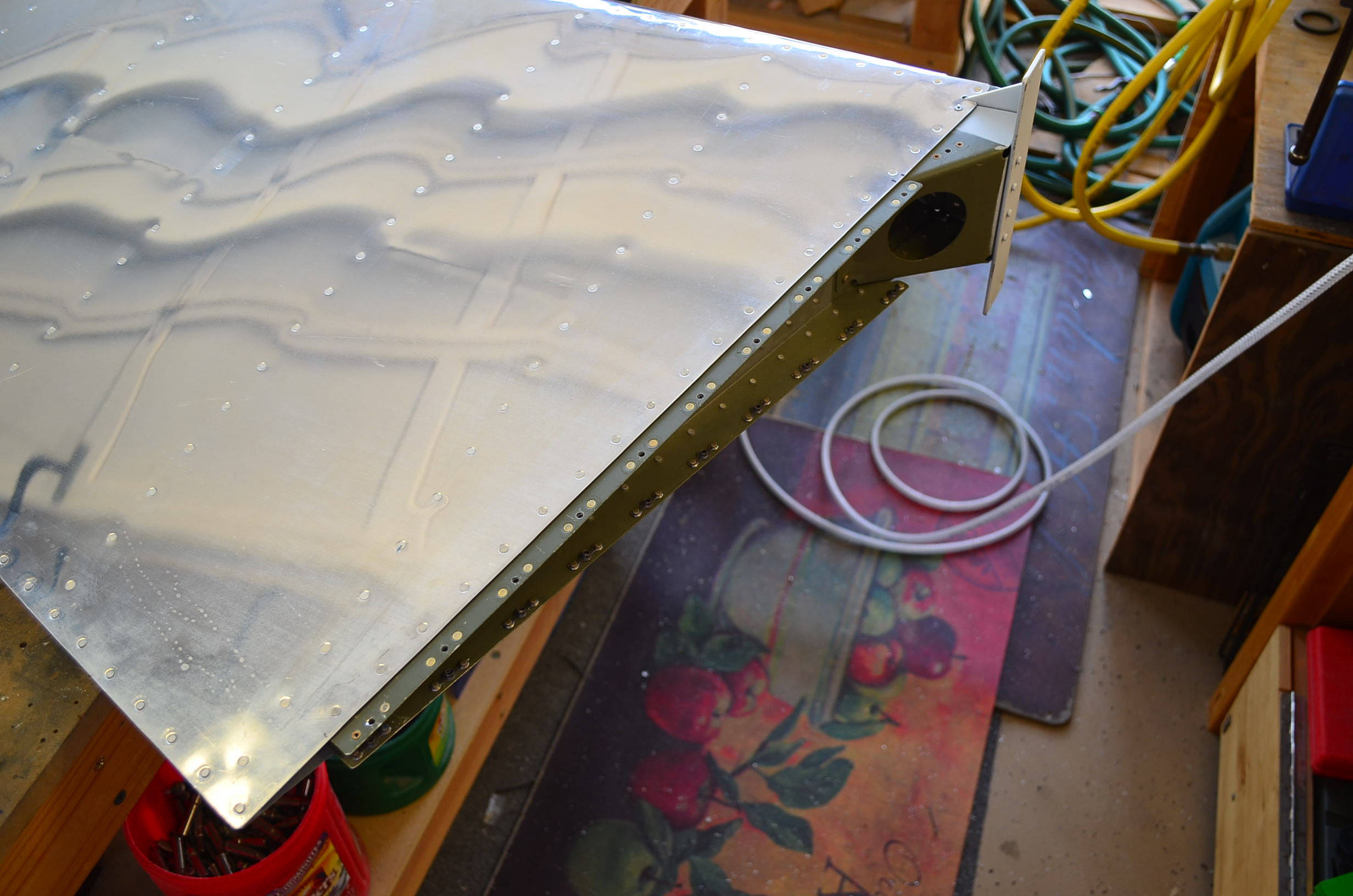
Another task on my list was to run a 1/4 inch tube from the firewall to the right fuel tank for the Airflow Performance fuel purge line. I had been dreading this task because there is no easy way to do this. The routing from the firewall to the tank is anything but direct and I knew bending the tubing would be difficult in these tight quarters. I decided to go through the right longeron with a snap bushing and get the line behind the right interior side panel trim as soon as possible, then go downward under the right rudder cable into the area of the right gear weldment which is covered by the carpet. You can see my final routing in this photo before I installed the side panel. I bent the section in front of the longeron first. Then I inserted the free end of the tube through the snap bushing and bent the remainder of the tube run to the tank in situ which was a big pain. I used a coil spring tube mandrel to prevent the tubing from flattening during bending. One of my goals was to keep the tubing away from the copilot’s feet and this accomplishes that goal.

The tubing comes through the side of the fuselage with a rubber grommet and points straight at the access cover of the right tank. I will have to line up and partially install the right wing to locate the correct spot to install a bulkhead fitting for this line so that will have to wait a while. For now I left the tube a little long so I can cut and flair it to length at that time.

Leg Fairings Aligned – 9 hrs
Sunday Feb 16, 2014
The gear leg fairings need to be aligned to the nominal airflow when the aircraft weight is off the landing gear. So while the wheels were off the ground I aligned the fairings using the method described in the manual. I hung a plumb bob from the aft edge of the fairing and measured the distances of that point vertically from the floor and out from the centerline. In this photo you can see the plumb bob marking the distance out from the centerline.

Then I set up a stool to establish a point the same distance up off the floor and out from the centerline under the horizontal stabilizer. I strung a piece of string from the stool to and around the fairing at the aforementioned point and pulled it tight. This represents the nominal air flow direction. I then adjusted the fairing until the aft edge bisected the two legs of the string and then tightened the hose clamp that secures the fairing to the leg. It took longer to set this up than it did to adjust the fairing.

After finishing the left main gear fairing alignment I set up to do the right leg but I realized I still needed to install the hinge for that fairing so I did that before I stopped working on Saturday for the night.

In the morning I installed the right leg fairing and aligned it to the air stream in the same way I did the left leg fairing. After that I realized I didn’t really need the airplane up off the ground on jacks any longer so I lowered it down and got the jack stands out of the way. I’m glad to have that done.

For a small diversion I decided to install the seat belts next. I have the Crow harnesses with camloc releases in black with black anodized hardware. Denise picked out the color. I like it because it accents the black instruments on the panel and the stick grips.

Right Main Gear Fairing – 2 hrs
Thursday Feb 13, 2014
Tonight I went through all the motions to align the right main gear fairing and drill it to mount to the fairing brackets.

I also trimmed the opening for the tire to provide about 1/2 inch clearance all around and sanded the edges smooth.

Fitting Gear Leg Fairing Clamps – 2 hrs
Monday Feb 10, 2014
Still plodding along on these landing gear fairings with fiberglass dust in my hair and dried out hands. Tonight I cut the notches in the main leg fairings for the hose clamps that secure them to the leg struts. These are cut on the inboard side and will be under the intersection fairings so they will not be visible. A straight notch did not provide full access to the clamp screw so I opened it up a little with my dremel tool.

Here is how it looks installed on the left leg. I followed the instructions and heated the fiberglass up with my hot air gun before tightening up the clamp to make the fiberglass more pliable and help it form to the cylindrical leg.

Here is a view from the inboard side so you can see the hose clamp screw.

I sanded the fiberglass on the inside of the wheel fairing where the brackets mount in preparation for liquid shimming the fairing with epoxy/flox. I put packing tape over the surfaces of the brackets then gooped up blobs of epoxy/flox on the inside of the fairing in the area of bracket contact. Then I put the fairing on the wheel, clecoed in place to cure for tomorrow.

More Fairing Work – 8 hrs
Sunday Feb 9, 2014
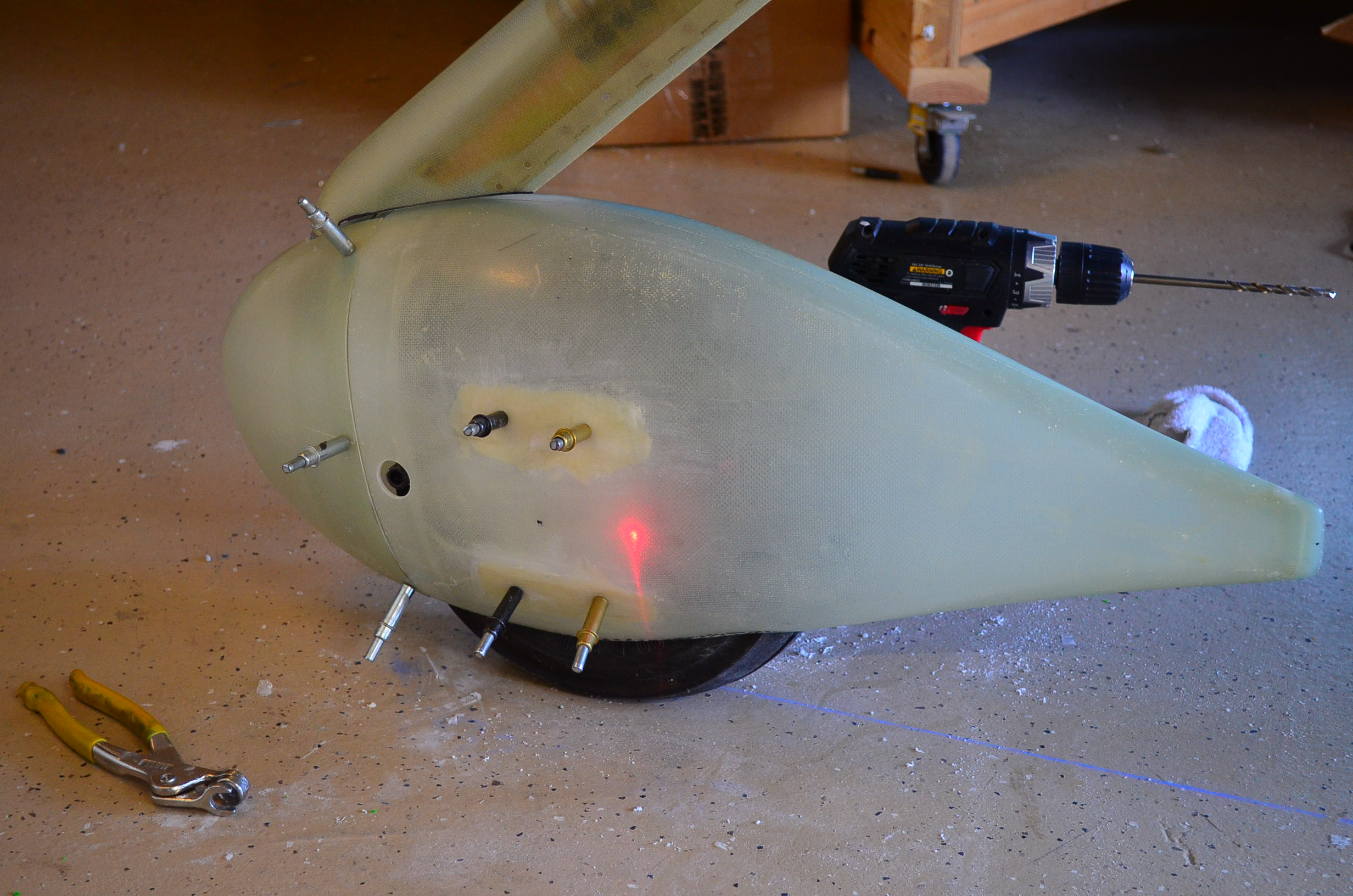
This nose wheel fairing is turning out to be more work than I expected. This weekend I wanted to try to wrap up the job of fitting it to the wheel brackets. I needed to drill three holes in the fairing; two for the two bar access and one for access to the air valve. To locate the proper location for the air valve hole I set up a laser level at the height of the valve and I pointed it directly at the end of the valve. You can see the red glow in this photo.

Then I put the fairing back on. The laser now shines directly on the fairing in line with the valve so that is where I drilled. I started out small and worked my way up to almost a inch diameter to fit the camloc access door I bought at ACS.
This next photo shows the fairing after I had installed the access door and drilled both holes for the tow bar.

I did a final trim of the cutout for the wheel to make sure I had adequate clearance then I mixed up some epoxy and painted on a layer inside the fairing to seal the surface with a non-porous layer. Then I set this out to cure.

I resumed work on the main gear leg fairing by installing the hinge which is used to close up the aft edge. This was basically the same process used on the nose gear leg fairing. I also cut the notches for the hose clamp that will hold the fairing to the gear leg.

I then checked the fit on the gear leg. I made another trim cut on the bottom edge and now this looks good to go. Not shown here are some reinforcement patches I laid up inside the left main wheel fairing in the areas where the brackets mount. I put down two or three layers of fiberglass to even out the surface of the fairing and make it more parallel to the bracket surface. I’ll still have to form epoxy/flox shims between the fairing and the brackets later to get the fit I want.

I also went out to Corona to look at hangars on Saturday. My search for a home base has officially started.

A really nice example of an RV7A by Byron Graves. I hope mine looks half this good

Build Phase
