Archive
Leg Fairings Aligned – 9 hrs
Sunday Feb 16, 2014
The gear leg fairings need to be aligned to the nominal airflow when the aircraft weight is off the landing gear. So while the wheels were off the ground I aligned the fairings using the method described in the manual. I hung a plumb bob from the aft edge of the fairing and measured the distances of that point vertically from the floor and out from the centerline. In this photo you can see the plumb bob marking the distance out from the centerline.

Then I set up a stool to establish a point the same distance up off the floor and out from the centerline under the horizontal stabilizer. I strung a piece of string from the stool to and around the fairing at the aforementioned point and pulled it tight. This represents the nominal air flow direction. I then adjusted the fairing until the aft edge bisected the two legs of the string and then tightened the hose clamp that secures the fairing to the leg. It took longer to set this up than it did to adjust the fairing.

After finishing the left main gear fairing alignment I set up to do the right leg but I realized I still needed to install the hinge for that fairing so I did that before I stopped working on Saturday for the night.

In the morning I installed the right leg fairing and aligned it to the air stream in the same way I did the left leg fairing. After that I realized I didn’t really need the airplane up off the ground on jacks any longer so I lowered it down and got the jack stands out of the way. I’m glad to have that done.

For a small diversion I decided to install the seat belts next. I have the Crow harnesses with camloc releases in black with black anodized hardware. Denise picked out the color. I like it because it accents the black instruments on the panel and the stick grips.

Right Main Gear Fairing – 2 hrs
Thursday Feb 13, 2014
Tonight I went through all the motions to align the right main gear fairing and drill it to mount to the fairing brackets.

I also trimmed the opening for the tire to provide about 1/2 inch clearance all around and sanded the edges smooth.

Fitting Gear Leg Fairing Clamps – 2 hrs
Monday Feb 10, 2014
Still plodding along on these landing gear fairings with fiberglass dust in my hair and dried out hands. Tonight I cut the notches in the main leg fairings for the hose clamps that secure them to the leg struts. These are cut on the inboard side and will be under the intersection fairings so they will not be visible. A straight notch did not provide full access to the clamp screw so I opened it up a little with my dremel tool.

Here is how it looks installed on the left leg. I followed the instructions and heated the fiberglass up with my hot air gun before tightening up the clamp to make the fiberglass more pliable and help it form to the cylindrical leg.

Here is a view from the inboard side so you can see the hose clamp screw.

I sanded the fiberglass on the inside of the wheel fairing where the brackets mount in preparation for liquid shimming the fairing with epoxy/flox. I put packing tape over the surfaces of the brackets then gooped up blobs of epoxy/flox on the inside of the fairing in the area of bracket contact. Then I put the fairing on the wheel, clecoed in place to cure for tomorrow.

More Fairing Work – 8 hrs
Sunday Feb 9, 2014
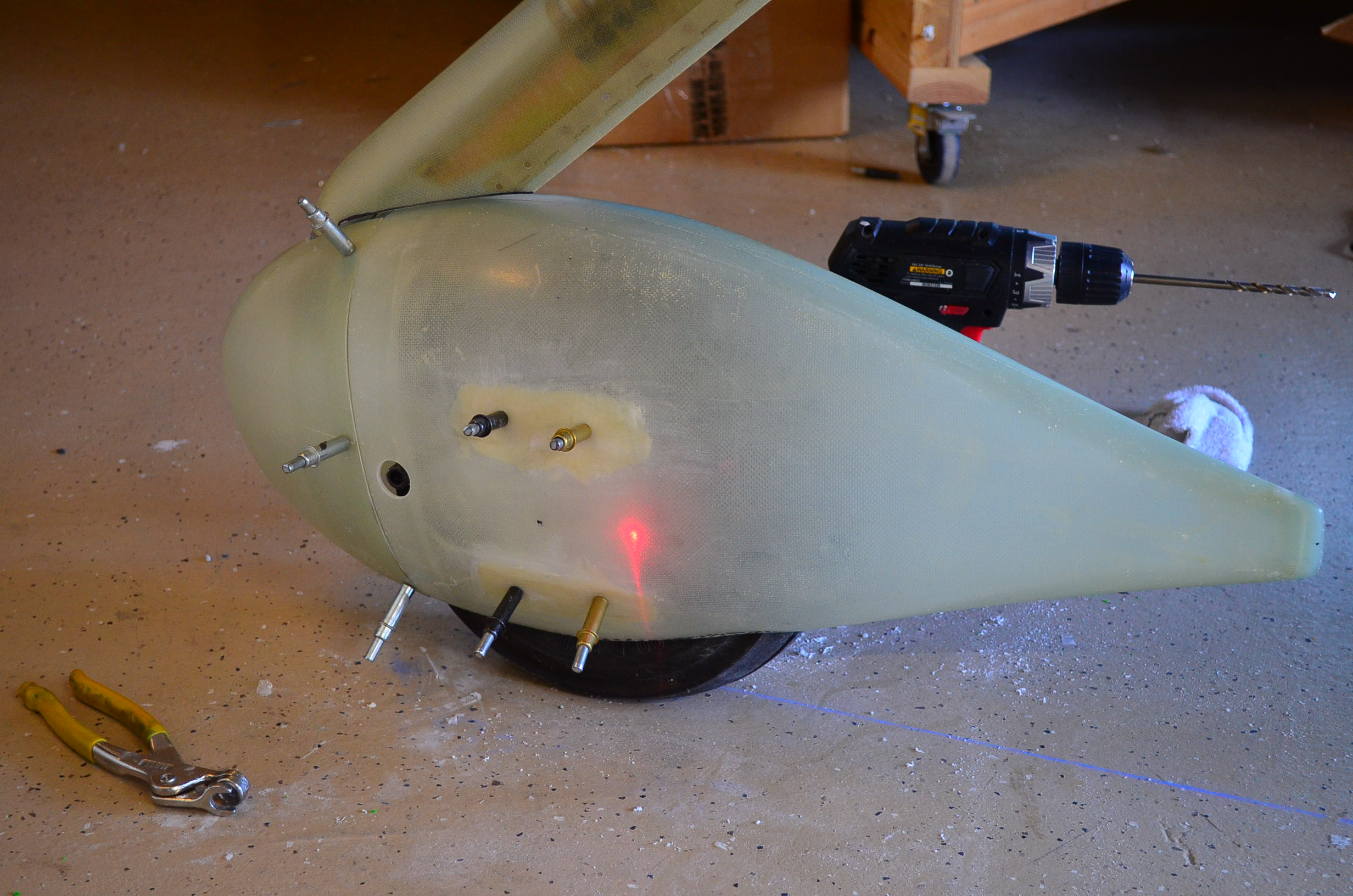
This nose wheel fairing is turning out to be more work than I expected. This weekend I wanted to try to wrap up the job of fitting it to the wheel brackets. I needed to drill three holes in the fairing; two for the two bar access and one for access to the air valve. To locate the proper location for the air valve hole I set up a laser level at the height of the valve and I pointed it directly at the end of the valve. You can see the red glow in this photo.

Then I put the fairing back on. The laser now shines directly on the fairing in line with the valve so that is where I drilled. I started out small and worked my way up to almost a inch diameter to fit the camloc access door I bought at ACS.
This next photo shows the fairing after I had installed the access door and drilled both holes for the tow bar.

I did a final trim of the cutout for the wheel to make sure I had adequate clearance then I mixed up some epoxy and painted on a layer inside the fairing to seal the surface with a non-porous layer. Then I set this out to cure.

I resumed work on the main gear leg fairing by installing the hinge which is used to close up the aft edge. This was basically the same process used on the nose gear leg fairing. I also cut the notches for the hose clamp that will hold the fairing to the gear leg.

I then checked the fit on the gear leg. I made another trim cut on the bottom edge and now this looks good to go. Not shown here are some reinforcement patches I laid up inside the left main wheel fairing in the areas where the brackets mount. I put down two or three layers of fiberglass to even out the surface of the fairing and make it more parallel to the bracket surface. I’ll still have to form epoxy/flox shims between the fairing and the brackets later to get the fit I want.

I also went out to Corona to look at hangars on Saturday. My search for a home base has officially started.
Started Fitting Main Gear Fairings – 5 hrs
Sunday Feb 2, 2014
This morning I fit the front and rear sections of the main gear fairings together. The joint required some work to get an acceptable fit. The rear section seems to be molded on a tool pretty accurately but the aft edge of the front sections were not straight resulting in gaps in the seams. I sanded the high spot off to get a good fit on one pair. The other pair will require some filler in one particularly low spot. I drilled and cleco’d the section together.

Based on a tip from Bruce Hill I trimmed the opening for the tire to enlarge it slightly and to even it out a bit. This photo shows the trim lines before I opened it up.

I installed the U-808 brackets for the fairings on the wheel nuts and taped a 1-inch thick block of wood to the top of the left tire. Then I began fitting and aligning the wheel fairing. Initially the fairing would only go on until it bumped into the gear leg but I marked the location and notched the fairing until it would go far enough forward to align with the U-808 bracket. This overall seems to fit better than the nose wheel fairing.

Here is a view head on to the tire. Notice that the angle of the fairing matches the camber of the wheel so the fairing is tilted outward relative to the ground. There is also a bit of toe in of the tire but the fairing is aligned to the free air stream which is parallel to the aircraft center line which is denoted by the blue tape. The U- 808 bracket actually fits pretty well.

When the fairing was aligned to as well as I could make it I drilled through the fairing into the predrilled holes in the U-808 bracket which I could see pretty well through the translucent fairing.

Then I put the forward section of the fairing on and continued to tweak the alignment to make the axis of the fairing parallel to the tape line. This is hard to judge because the fairing is tilted outward but I got it aligned as well as my eye could judge. Then I drilled through the fairing into the U-810 bracket holes on the inboard side. Afterward, I marked the opening around the tire and trimmed a little more away for clearance. It is getting close but I am still not done there.

I did not take a photo in process but I also countersank and riveted the hinge in the nose gear leg fairing. I installed it to see if it fits with the anti-splat mod installed on the leg. Thankfully it just fits.

Preparing to Install Main Gear Fairings – 8 hrs
Saturday Feb 1, 2014
This weekend was my first chance try out the jack stands I built to lift the fuselage and take the weight off the landing gear. This is needed to install and align the main gear fairings (pants). I used the engine hoist to lift the engine mount to level the longerons so the aircraft support is on three points. It is quite stable and I don’t have any concerns about the stands tipping over so I can leave the airplane this way for a while.

First thing I needed to do was install the wheel fairing support brackets. I fit these to the wheels a long time ago but I found that I needed to trim down the three tubular spacers about 0.1 inch to get the gap to the bracket set in the .032 -.094 range called for on the drawing. That took a while but I got everything back together again with the brackets installed and ready to receive the fairings.

I dropped a plumb line from the center of the firewall and another from the tie down ring on the tail and snapped a chalk line between them to mark a centerline for the aircraft. Then I measured out about 40.25 inches in tow places and snapped another chalk line parallel to the centerline but passing through the centerline of the tire where it touches the ground. I did this on both sides of the aircraft. These are my lines to which the wheel pants will be aligned.

Back on the nose gear fairing, I mixed up some epoxy with flox and I gooped it up in between the nose gear fairing and the brackets. These brackets don’t sit flush on the fairing surface and the epoxy is to form a shim that makes the connection solid without distorting the fairing. After installing the wheel fairing I checked the alignment and then left it alone for about 3 hours while the epoxy cured. I switched out the clecos after that to make sure I did not epoxy those in place and let it cure another 2-3 hours.

After that I took off the leg fairing and started fitting the hinge that holds the rear edge together. Here you see it drilled and cleco’d to the fairing. I trimmed the hinge to length but I left the hinge pin long for now.


A really nice example of an RV7A by Byron Graves. I hope mine looks half this good

Build Phase
