Archive
Top Forward Skin Riveted On – 4 hrs
Sunday May 4, 2014
I waited as long as I possibly could to do this but today I finished riveting the top forward skin onto the fuselage. With this on access to the area behind the subpanel is only from below and it is much harder to get under there to work but I had checked everything else off the list of things to do before moving to the airport. So now this bird is ready to go to her nest and get her wings attached for good. I just have to nail down the arrangements for a hangar.

Made Access Panel for Fwd Upper Skin – 12 hrs
Sunday Mar 23, 2014
I find my list of things to do before I move the airplane to the airport is getting shorter although I occasionally find things I overlooked to add to the list. This weekend I took on the mini-project to add an access panel to the upper forward skin of the fuselage. I mean the skin immediately in front of the tip-up canopy. There are quite a few components under this skin, like the VP-X Pro unit, EMS module and the entire array of ground terminals. I have been concerned about access to this area after the skin is riveted on, which will be soon, and I have seen other builders install an access panel or two here so the idea got under my skin (pun intended).
I started by laying out the location for the panel on the skin itself with a sharpie. I also made a scale layout in AutoCad to lock down the dimensions. I cut the new access panel and the doubler I needed from .032 stock sheet. Then I cut the opening in the top skin with the thought that if this does not work out well I can always order a new skin from Vans.

To ensure a good fit I put the skin on the fuselage to match drill for the rivets that will attach the doubler to the skin since the skin is curved when installed. I started in the middle of the opening and worked my way out to the edges.

This is how it looked with all the rivet holes drilled and clecoed. There are lots of rivets to help reinforce the skin around the perimeter.

After deburring and dimpling the skin and doubler and spraying on a coat of primer I put the skin back on the fuselage and riveted the two parts together.

Then I laid out the hole pattern on the cover plate for the mounting screws, match drilled it, and installed countersunk nutplates for #8 screws.

This is how it turned out, with only four screws installed for now because it will come off again for a while before the skin is riveted to the fuselage. The access hole is not huge but it provides good access to the VP-X, the ground block and several connectors that would be really tough to get to without the access panel.

I also finished wiring up the Nav/position lights and landing light on the left wing tip.

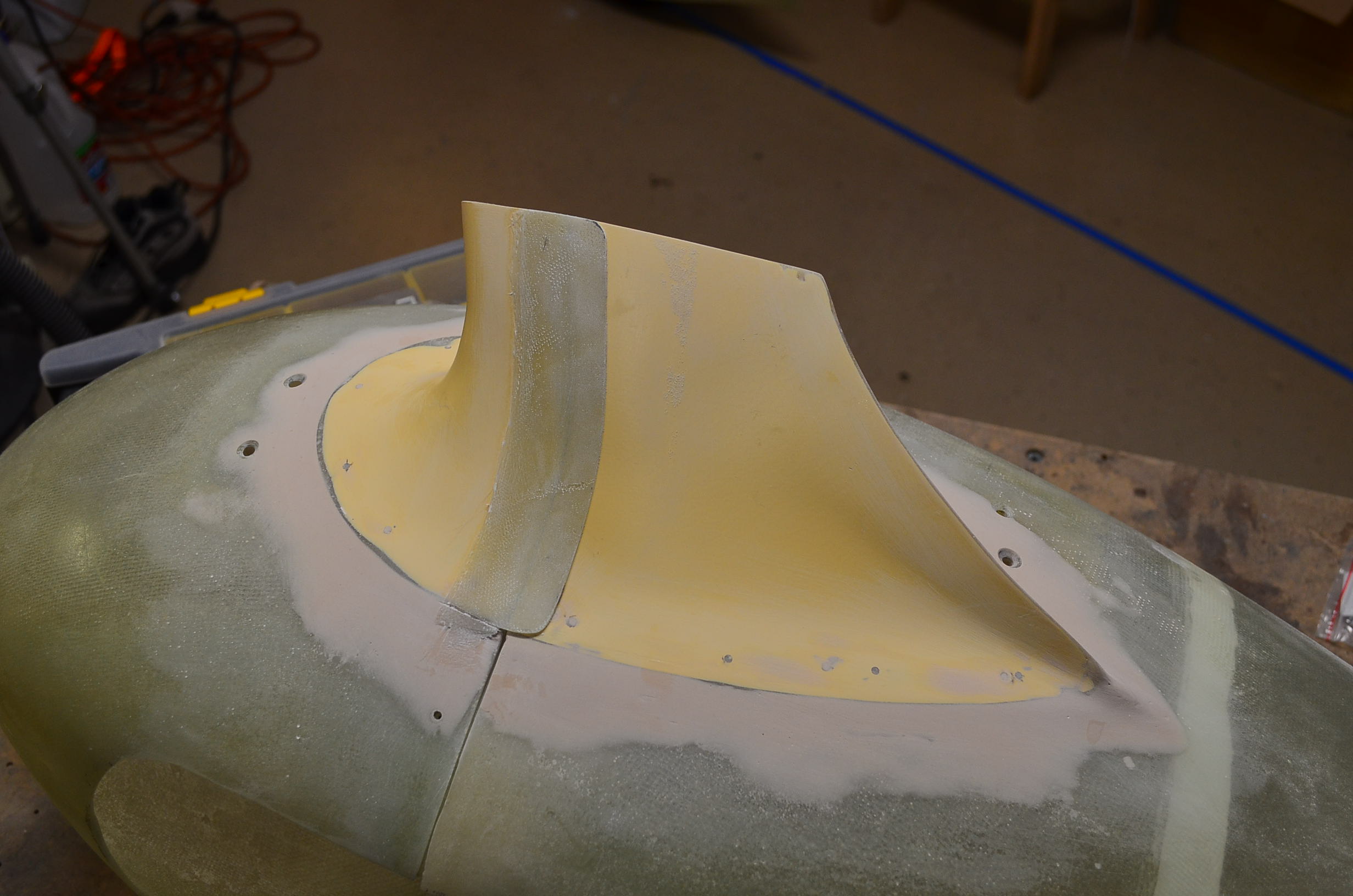
Intersection Fairings – 20 hrs
Sunday Mar 2, 2014
I was out of town last weekend with the wife and for a couple more days this week on business so progress was delayed.
With the gear leg fairings aligned it was time to start installing the lower intersection fairings on the wheel pants. I purchased mine from Cleaveland Aircraft but they are actually made by RVbits. These are supposed to be better quality than the Vans parts. After aligning them to the leg and wheel fairings I match drilled a set of #40 holes to cleco them in place. I then marked a line to cut the intersection fairing into three pieces so it can split with the front and read wheel fairing sections. After wrapping the gear leg fairing with packing tape I mixed up some epoxy with heavy flox and bonded the three pieces back onto the wheel fairing as well as bonded the aft edges of the intersection fairing together. I did this all in place on the gear leg to make sure everything was fitting well. Here is one clecoed together and set up to cure.

After the epoxy was set I sanded the surfaces to remove excess epoxy. I applied more packing tape over the aft section of the intersection fairing and laid down three layers of fiberglass overlapping the seam between the front and rear sections to make flaps attached to the front section that overhang the aft section along the gear leg fairing so the air stream cannot get under the aft fairing and lift up the forward facing edge. I took this picture after I removed the fairing sections from the landing gear and clecoed them back together. Here you see the raw fiberglass layup.

With the two sections separated you can see the fiberglass is bonded to the front section and simply overlaps the aft section. The edges of the layup are still raw.

After trimming the edges to leave 1/2 inch overlap and sanding the surfaces the parts look like this.

Here I put it back together again to show the finished overlap on the bottom edge.
When I was happy with the flaps on the left side fairing set I mixed up more epoxy with micro and smeared it on to smooth out the transitions between the parts including the front and rear wheel fairings which are not very flush along the seam. This photo is before sanding the micro.

I received two hoses I ordered from TSFlightlines for the brake lines down the landing gear legs. I installed the left hose to verify the length. It looks good so I installed it using three short pieces of plastic tubing and electrical tape to strap it to the leg.

I sanded the micro on the left wheel pant and intersection fairing using several coats of epoxy to get it well blended and smooth. I also sanded the entire exterior of the both the left wheel and leg fairing. Then I installed K1000-6 nutplates on the aft wheel pant section for the screws that hold the two sections together. After more hours of work than I expected this set is finally complete including the lower intersection fairing and is ready for primer. I just need to get the right set up to the same point.

Another task on my list was to run a 1/4 inch tube from the firewall to the right fuel tank for the Airflow Performance fuel purge line. I had been dreading this task because there is no easy way to do this. The routing from the firewall to the tank is anything but direct and I knew bending the tubing would be difficult in these tight quarters. I decided to go through the right longeron with a snap bushing and get the line behind the right interior side panel trim as soon as possible, then go downward under the right rudder cable into the area of the right gear weldment which is covered by the carpet. You can see my final routing in this photo before I installed the side panel. I bent the section in front of the longeron first. Then I inserted the free end of the tube through the snap bushing and bent the remainder of the tube run to the tank in situ which was a big pain. I used a coil spring tube mandrel to prevent the tubing from flattening during bending. One of my goals was to keep the tubing away from the copilot’s feet and this accomplishes that goal.

The tubing comes through the side of the fuselage with a rubber grommet and points straight at the access cover of the right tank. I will have to line up and partially install the right wing to locate the correct spot to install a bulkhead fitting for this line so that will have to wait a while. For now I left the tube a little long so I can cut and flair it to length at that time.

Installed Transponder Antenna – 9 hrs
Sunday Nov 18, 2012
This post summarizes most of the things I did this weekend on the project.
On Friday the transponder antenna I ordered from Delta Pop Aviation arrived in the mail. This is a low drag blade antenna that I will mount on the bottom of the fuselage just behind the baggage bulkhead. Delta Pop also has a UAT ADS-B antenna that looks identical that I also plan to install when I get around to ordering it so I made two identical doubler plates. I want to get the metal work done now before I install the rear canopy window.
Because the antennas are narrow I bent the doubler plates on each end to add ribs to help spread the loads laterally into the skin. I would have used .040 thick alclad for these but all I had was .032 so I used that.

I used the doubler plates as templates to drill the holes in the fuselage skin. This view shows the transponder antenna doubler location on the right side of the fuselage.

Here is the UAT antenna doubler on the left side. At these locations the two antennas will be two feet apart – the minimum recommended distance. The will also be about 3 feet from the comm antennas which I plan to put under the seat pans just aft of the spar.

For installation I followed the recommendations on the EAA website for this type of antenna. I used star washers under the lock nuts to get good electrical grounding and I put a bead of Alex Plus siliconized caulk on the face of the antenna to seal out water. The benefit of this material is it won’t interfere with paint adhesion around the antenna when the day comes to paint this baby.
After I torqued down the screws the antenna seemed pretty solidly attached so I think the .032 alclad was adequate. Still this thing is somewhat vulnerable sticking down here no matter how thick the doubler is and I’ll have to be careful not to bang into it.

I also riveted the outboard subpanel ribs to the forward fuselage. This photo shows some of the more difficult rivets. I left the center subpanel clecoed because I will need to remove it to cut a hole for the radio stack trays which are longer than about 8 inches. Right now I expect that will be the SL-30 and GTN-635 trays.

I also played around with a bracket for the headphone jacks. I’m trying to decide where to put these and one option is on a small bracket slightly recessed behind the panel near the air vents. My only question with this location is whether it will be in the way of passenger knees. I made a sample bracket and clecoed it to the panel edge as an experiment. Still undecided. I wish I had seats installed so I could judge it better.

I also did some electrical work. Since I installed the Skyview network hub last week I cut the wires on the ADAHRS I had routed to the forward fuselage and terminated them with a Dsub connector. Now the ADAHRS plugs into the hub. I also installed another Dsub on the remaining 15 foot long run of wires I cut to make a network cable for the run to the panel. I mated that connector to the hub also and ran the wires down the right side of the center tunnel. So far it does not look like I reduced the overall wiring with the hub located here but I still have wires from the pitch and roll autopilot servos to run. The control signals for those will also get routed to this hub so it will ultimately have four out of five ports occupied.

Installed Heater Box Cable – 1.5 hrs
Saturday Nov 7, 2012
Tonight I installed the cable that opens and closes the heater box valve to regulate warm air flow into the cabin. The cable appears to be a couple of feet too long and I can’t do the final installation until the instrument panel is installed but I wanted to get everything set up now while I have good access to the valve through the firewall recess. The standard installation method is to mount an Adel clamp using the heater box screw but when I did that the cable was bent awkwardly so I modified the approach by making a bracket from 3/4 x 3/4 aluminum angle and I mounted the Adel clamp to that. This results in less bend of the cable and smoother action. It also moves the cable far enough aft that I did not have to drill a hole in the firewall rib for the cable.

I installed the F-782 also and saw that I needed a notch to allow the cable to pass. You can see the notch I made in this picture. I have a small rubber grommet that will fit in this notch nicely but I will wait for the final installation to insert that.

Installed Fuel Pump Connector – 1 hr
Monday Nov 5, 2012
I only had about an hour tonight so I installed a Molex connector on the fuel pump wires (both sides of the connector are mated here) and mounted two zip tie bases on the F-782 to secure the wires. Those zip ties will also keep the connector secured in place.

Then I put the fuel pump section back in the cabin with the fuel transfer line to the firewall. Now the area in front of the pump is wide open for routing wires until I install the front section of the F-782.

Repacked Wheel Bearings – 1.5 hrs
Wednesday Oct 24, 2012
I originally hand packed the main landing gear tapered roller bearings with grease but I had lingering concerns that they may not be fully packed. After all, I’m not an experienced packer. So I ordered this Lisle bearing packer from Amazon for about $10. A good investment in my book. I also ordered a grease gun which I need to fill the nose gear swivel bearing anyway. I could have bought a grease gun at Home Depot for $15 but the one I bought is way better quality for $18.

The packing process is simple. You sandwich the bearing between the upper and lower cones and then pump grease into the bearing through the center screw with a zerk fitting attached. When you see the grease oozing out between the rollers the bearing is packed.

I also decided to modify the right F-745 rib of the front fuselage structure to permit the installation of a second 10-inch Skyview display. So I cut the rib at the front surface of the sub-panel and touched up the edge with paint. When I clecoed the rib back into the fuselage it made it symmetric with the left side. So later I will make angles to mount the remaining aft sections of the two F-745 ribs to the subpanel closer to the centerline between the Skyview and the radio stack.

Redo Fuel Vent Line, Rudder Pedal Installation – 6 hrs
Sunday Mar 4, 2012
When I initially installed the front deck components I found that I had an interference with the fuel vent lines. The lines route along a diagonal near the top of the F-902 bulkhead but my diagonals are too small and the flange of the F-768 sub-panels interfered. Either the flanges needed to be notched or the lines need to move. I simply loosened the Adel clamps on the lines at that time and kept building. Today I determined to fix that problem. After futzing with the left line for a while I found that I could not tweek it enough by rebending the diagonal to clear the F-768 flange so I decided to remake the whole line. I had the old line as a guide which helped but it still took a over an hour to make a new line. The result is seen below. The upper diagonal now starts about one inch above the upper Adel clamp. The F-768 clears the line and the line easily clears the NACA duct which I placed on the opening just to make sure.

Here is a view with the F-768 clecoed in place. The flange right below the cleco is the problem area.I wish I knew this before I made the vent lines the first time.

I was able to tweek the right vent line and make it fit because I had a larger diagonal to begin with and I was able to lower the first bend and shift the upper segment forward about one inch.
When I was working on the wing root fairings a few days back I found that the large AN fitting washers on the outside of the fuselage for the vent lines were almost rubbing the fairings. I need clearance for the gap seal strip there. So while I was working on the vent lines I removed the large AN fitting washers to grind a bit off the front edge. A primed them with SEM self etch and reinstalled them on both sides. You can see one in the photo below.

Back to the front deck parts. I riveted the F-768 outboard sub-panels to the F-745 ribs using just the two top rivets which are flush style.

Then I set up the sprayer and painted the aft face of the sub-panel components and the F-745 ribs aft of that. These parts will be visible when the canopy is raised and I want them to look good. The Jetflex is also more durable than just the primer so that is an added plus.

It is time (I think) to install the rudder pedals and brake lines. So I started by installing the fittings on the brake cylinders using Locktite 567 sealant on each fitting. This is the recommended sealant on the forums.

Next up are the plastic lines that connect the brakes to the reservoir and between the left and right cylinders. When I tried to install the first insert and ferrule I was stymied. The insert does not want to go into that hole. I tried soaking the end of the line in boiling water but that still did not do it. After researching the problem on the forums I found a tip about making a simple tool to assist. So that is what I did. It’s just a cut-off nail in a piece of wood (preferably hardwood). You can see my attempt below with one of the fittings set up to press in.

After soaking the end of the tube in boiling water for about 30 seconds I put the insert over the nail and pressed down as hard as I could. The nail keeps the tube from buckling over so you can apply more force. That did the trick. This is still not easy, but they are going in now.

He is a shot of my partially completed brake lines. I Installed the two lines on the right side to the reservoir and began running the two lines that connect the right brakes to the left brakes. I also drilled two holes in the upper rudder pedal tube support and installed snap bushings for the two transfer lines. That is where I quit for today. More to come tomorrow.

Finished Right Wing Bottom Skin Riveting – 4 hrs
Friday Dec 23, 2011
Yahoo! I finished closing up the right wing this morning. It took about an hour and a half to finish riveting the last two ribs and the front and rear spar sections between them on the outboard bottom skin. Here is a view of the finished wing still on the work table.

A package arrived from Tower Hobbies today with the control rod hardware I need to mount the Ray Allen POS-12 position sensor for the flaps. I got this parts tip from Mike Bullocks web site. Here are the parts I ordered. You can see Mike’s installation here.
| LXK088 THREADED COUPLER 2-56(0.074″), 2 ea. |
| LXK064 THREADED PUSHROD 2-56X12″, 6 ea. |
| LXK077 STEEL CLEVIS 2-56, 12 ea. |
And here are the parts. I need one coupler, one pushrod, and two clevis’s for the flap setup but I may use the same approach to install an elevator trim position sensor also so I have extra hardware I can use for that.

I was at Lowe’s this morning and I picked up hardware store bolts for the upcoming wing assembly to the fuselage. I bought eight 7/16 bolts that are 4 inches long and one that is 6 inches to make a drift pin. In this picture you see one of the four inch bolts and the six incher that I modified. I cut off the threaded portion and ground the end of the shaft to a slight taper.

The bad news today is I tried to run the drift pin through the holes in the main spar and I found that it hangs up tight on the landing gear weldment holes. It seems that the holes are not quite large enough or are slightly off center to the spar holes. I wish I had discovered that before I “permanently” installed the weldments a couple months ago. Back when I installed them the plans warned me that I might need to file the holes for the weldment mounting bolts but I did not check the holes for the main wing bolts. My mistake.
So I started the process of removing the weldments so I can file the holes into submission. I got the left weldment removed and filed before I ran out of time (and steam) today. I still need to final torque the weldment bolts on this side.

More Right Wing Bottom Skin Riveting – 4 hrs
Thursday Dec 22, 2011
Ok, so I admit I am bouncing back and forth a bit between different parts of the project but that variety makes it more fun. this morning I finished building the right fuel vent line. No I didn’t screw it up on the last bend.

Later I continued riveting on the right outboard bottom skin. Here is one of the “down under through the hole” positions used to rivet along the aft spar. The skin is being held up by a string attached to a hook on the ceiling. Photo courtesy of my daughter Jessica.

I finished all but the last bay. The rest will be easy to set by comparison but I’ll have to finish those tomorrow.


A really nice example of an RV7A by Byron Graves. I hope mine looks half this good

Build Phase
