Archive
Installed Rudder Fairing, etc. – 9 hrs
Sunday April 20, 2014
Easter weekend, so happy resurrection day! I had the chance to fly an RV-7 (N223J) on Saturday with Jake Lewis, a neighbor in Mission Viejo and resident of a hangar at KAJO. We flew out to San Clemente and up the coastline to Huntington Beach. He let me pilot from the right seat most of the time. It was a blast. So much different than the C172 and I am anxious to put the spam can days behind me.
Back at home after lunch I completed the final installation of the lower fairing on the rudder. I had drilled pilot holes but I needed to install nutplates and countersink the fiberglass for Tinnerman washers. Here is a view of the nutplates installed along the attachment strip.
And here is a view with the fairing installed with the washers. I guess I could have spaced the screws out a little more and used fewer. This thing is on solid.

I also made and installed a tab for the local electrical grounding of the strobe light. I needed to ground the cable shielding on both ends to minimize EMI concerns but there was no convenient place to screw down the ground lug. So I made a tab, installed a nutplate on it, and riveted it to the bottom rib of the rudder.

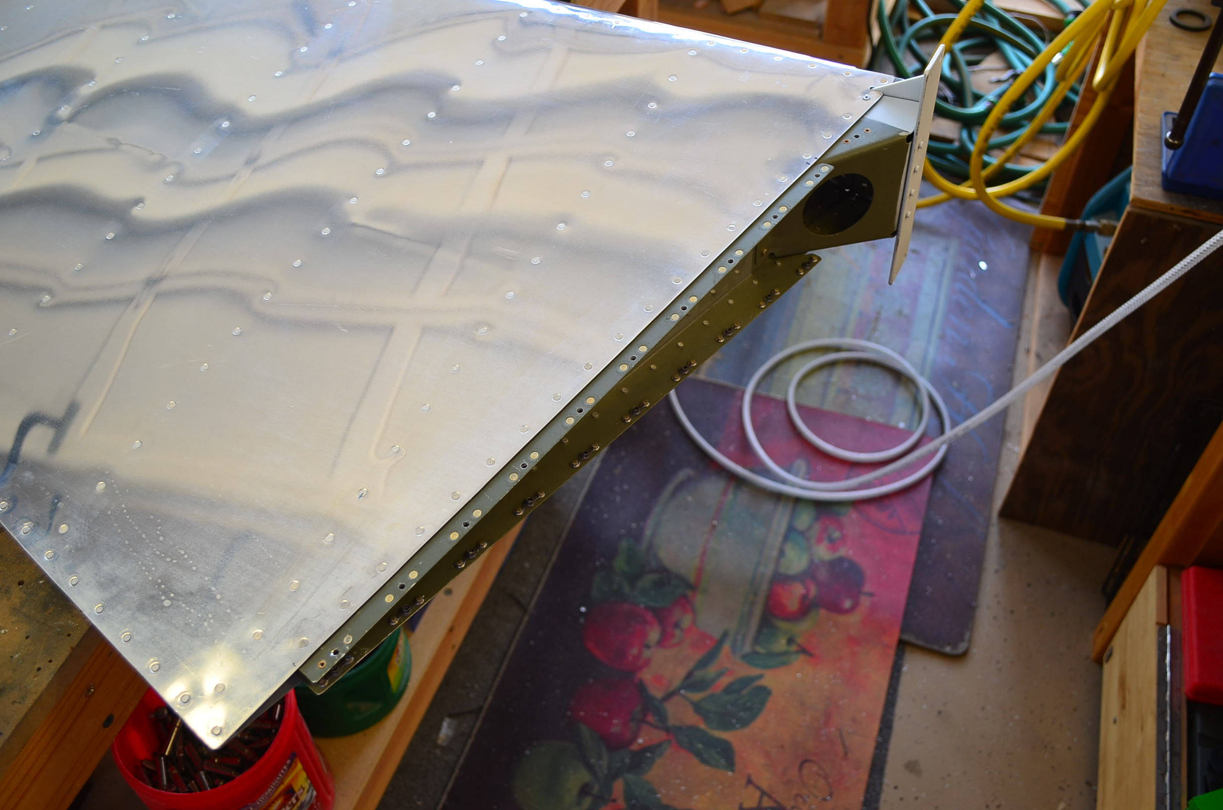
On Sunday evening after getting home from my daughters place I installed the nutplates on the horizontal stabilizer for the empennage fairing. Here is a view of the fairing test fit.

The list of things to do before moving to the airport is getting shorter and shorter.
Torqued Gear Bolts, Installed Static Ports – 2 hrs
Saturday Nov 19, 2011
Continuing this morning on the landing gear weldments I torqued all the bolts and striped them with torque seal. In this photo you can see the AN3 bolts that come in from the left side of the fuselage.

In this view you can see the AN4 bolts that attach the weldment to the main spar. It is nice to have this milestone completed.

Next on my list to do is to install the static ports and lines to the Dynon ADAHRS which will mount in the aft fuselage. I am using the SAFEAIR1 kit that comes with ports, fittings and plastic tubing. I started by marking the fuselage for the holes for the ports. I used the location recommended by Vans but I moved them forward a little to 1.125 inches ahead of the rivet line on the bulkhead to provide enough room for the rear flange of the port. I drilled the holes using a #40 drill then opened them up to .250 using a unibit. As you can see I scuffed up the interior surface of the skin because I will be bonding the ports using ProSeal.

I installed the tube fittings onto the static ports first to make sure I bonded them in with the orientation correct. It’s kinda nice that these fittings come with some kind of sealant applied on the threads so you just screw them in. Then I buffed the surfaces of the flanges with scotchbrite and cleaned them with MEK. I mixed up a small batch of ProSeal and applied a thin layer on the flange surfaces and put them in the fuselage orienting the fittings angled toward the bulkhead where the line will run. I taped them in place to hold them while the ProSeal cures which will be a while because it has been in the 50s and 60s in the garage.

Here is what it looks like from the outside. Very clean and yes it is supposed to protrude out from the surface of the skin slightly.

Installing Tail Light Adapter – 2 hrs
Saturday July 31, 2010
Denise spent the whole day cleaning out the garage yesterday. I didn’t ask her to, she just decided that I could work more efficiently if the place was more organized and uncluttered.

She is right. It’s a pleasure to be out here now and I feel like I am ready to start the wings.

In the mean time I am working on dismantling one of may patio covers to replace some rotting beams. That is no fun. I can’t stay away from the airplane factory completely so I scotchbrited the tail light adapter and cleaned it. Then I sprayed on a good coat of primer and let it dry in the sun.

Then I used CS4-4 pop rivets to mount it to the rudder bottom fairing. It was a little tricky because of the counterbores in the adapter. The nose of the rivet puller won’t go down in there so I stacked up six small washers on the rivet head when I pulled it. That did the trick and all the rivets were set flush to the bottom of the counterbore. Here it is ready to receive the tail strobe light.

Tail Light Adapter Part 1 – 1 Hr
July 29, 2010
My tail light adapter and tank dimple dies arrived from Cleveland Aircraft Tools today. I’ll need the dimple dies when I get to the fuel tanks but for now I can install the tail light adapter on the rudder bottom fairing. Here is the little $17 aluminum part.

I aligned it to the fairing contour by eye (a little awkward) and match drilled the holes in the fairing. The alignment turned out OK in spite of the fact that the fairing is not perfectly symmetrical.

Then I marked the center hole on the fairing and drilled it out using a 1 inch spade bit from my woodworking supplies. That worked surprising well. Then I smoothed out the edges of the fiberglass with my rotary tool and a sanding drum.

Ready to prime the adapter and install it with CS4-4 rivets.
Installed Horizontal Stabilizer Tips – 1.5 hrs
Sunday July 18, 2010
Today I permanently installed the horizontal stabilizer tips. I match drilled all of the holes to #30, then removed the tips and cleaned out all of the chips. Then I dimpled the holes in the skin using my pneumatic squeezer. Next I countersunk the holes in the fiberglass using a countersink head on a manual drive handle. Then I installed the tips using CS4-4 pop rivets.


The fits between the tips and the skins are quite good. The seams are tight and the leading edges line up nicely. So I am thinking about leaving these alone and not filling the seams with dry micro. I think I’ll move on to the rubber bottom fairing and that will give me some time to think about it.
Finished Elevator and Rudder Tips – 4 hrs
Saturday July 17, 2010
Big day today. I officially finished the elevator tips, rudder top tip, and vertical stabilizer top tip. The morning started with sanding out the dry micro that I applied last night on the VS tip seam. After shaping and blending it into the skin and the fiberglass there were several low areas where more filler was needed so I mixed another batch and applied that.
It was hot again today so it only took a few hours for it to kick over. Then I sanded it again to get the final clean shape I wanted. Seam gone!
Next I broke out the spray gun and sprayed on a few light coats of UV Smooth Prime, which I had learned about on the forums. It fills pin holes and small defects and sands out really smooth. It also provides UV protection to the fiberglass. I guess that’s important. It drys pretty fast too in light coats so it was only about a half hour before it was ready to sand.
Here is the finished VS tip.

Then I sprayed UV Smooth Prime onto the two elevator tips and the rudder top tip. I’m new to working with fiberglass so I am happy with how well these came out.
Here are the two elevator tips.


Here is the rudder top tip.

And here is how the rudder and VS tips fit together.

Here is a closeup of the gap.

I retrospect I am glad that I have time before my wing kit arrives (week of August 8 according to Vans) to finish the fiberglass on the empennage. Most builders postpone it until after the wings and fuselage are done. But I would rather get this dusty stuff done and out of the way. If the wing kit was already here I am sure I could not resist the temptation to focus on that because there is so much satisfaction in seeing the big pieces come together. But now I know how time consuming the fiberglass work can be if you have a perfectionist approach, which I sorta do. It has take a lot more hours than I ever expected and I learned a lot. Hopefully something I posted here may help someone in addition to documenting my process for the FAA.
Ah, but I get ahead of myself. Next: Filling the seams on the horizontal stabilizer tips and installing the rudder bottom tip.
Rivet On the VS Tip – 2 hrs
Friday July 16, 2010
Today after work I decided it was time to permanently attach the vertical stabilizer fiberglass tip. I had already match drilled and dimpled the skin so it was just a matter of riveting it on with CS4-4 pop rivets. I want to make it as clean as possible so I mixed up a small batch of epoxy and applied a strip of deck cloth over the seam. I used a layer of peel ply over that to minimize the sanding later.

I was hot today ( in the 90s) so the epoxy kicked over really fast. It was hard and sandable in two and a half hours. So I sanded the small amount of glossy epoxy that wasn’t under peel ply and then slathered on a layer of dry micro across the seam and over the end row of rivets on the skin.

Tomorrow I’ll sand this out and see if I can get a smooth transition from the aluminum skin to the fiberglass.
Apply Primer to Rudder Tips – 1.0 hr
Sunday, July 11, 2010
I pulled out the spray gun yesterday and applied a coat of West Systems primer to the rudder and vertical stabilizer tips today so I could see any remaining imperfections in the finish and shape. Today after it was well dried I took these two photos.

The finish and shape are just about the best I could hope for. There are just a couple of very minor surface defects that can be fixed easily and a few pin holes. I’ll do a little bit of filling and then apply a coat if UV Smooth Prime to kill the pin holes. Then I’ll rivet on the VS tip and fill the seam between the fiberglass and the skin.Then these babies will be done until the ultimate paint job is applied.

Finish Tuning Rudder Tips – 2.0 hrs
Thursday July 8, 2010
Last time I added filler to the rudder and VS tips to fine tune the shape at the top edge. Tonight I sanded out the filler on both parts to get to the final shape. I am pretty satisfied with the results. There is one tiny dimple that I will fill next time I mix dry micro. The edges are now almost flush with the VS tip very slightly taller than the rudder tip at the intersection. That makes sense to me because the VS tip leads in the air stream.

Here is the shape looking straight down from the top along the hinge axis. That gap is about 0.100 inch.

Here is the rudder tip leading edge with the rudder rotated for a left yaw.

This weekend I plan to spray on a coat of West Systems primer to check for any minor flaws that are hard to see right now. If all is good then I will permanently rivet the VS tip to the VS and begin the process of filling and sanding the gap between the two pieces.
Fine Tuning Rudder Tips Part 2 – 1.0 hr
Tuesday July 6, 2010
Part 2 of this task starts with sanding the tip of the vertical stabilizer to shape the dry micro closer to the desired match with the rudder. Using 80 grit to rough sand it first then 220 grit to smooth it out this process took about 15 minutes. Here is the result. Not perfect but closer to the desired profile.

Next I decided to decrease the radius on the top trailing edge of the VS tip. I have found that making a tape dam to contain the dry micro is helpful so that is what I did.

The radius on the leading edge of the rudder tip seemed kinda large also so I made a dam there and added some filler to allow me to reduce the edge radius when I sand it out. So now these need to cure up and I will sand them tomorrow.


A really nice example of an RV7A by Byron Graves. I hope mine looks half this good

Build Phase
